Design for circular economy within a bicycle life cycle
The aim was to design a product for a circular economy, to reduce unnecessary and excessive waste from bicycle drivetrains during the use and disposal phases.


The problem
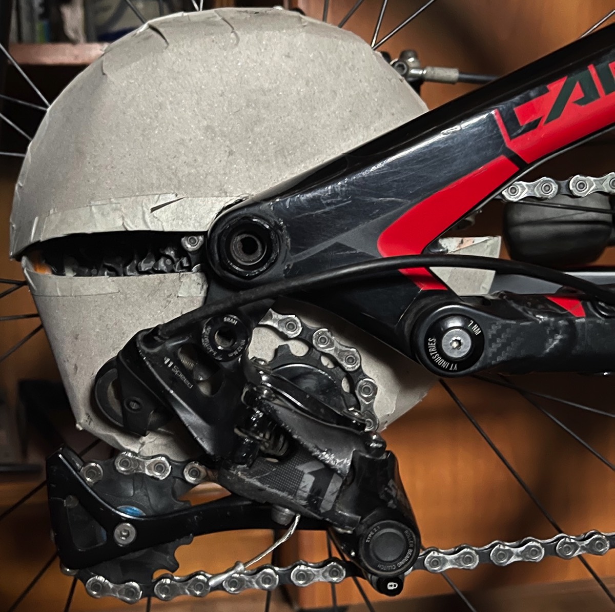
The drivetrain was chosen due to it being easily overlooked and its importance to the overall functionality of the bicycle. Additionally, the drivetrain is positioned low to the ground, in direct contact with dirt and debris. Therefore, making it particularly susceptible to getting damaged.
Research question
How can different bicycle drivetrains be constantly cleaned within a tidy operation, to ensure better functionality, prolong component lifetime and be done conveniently?
Key research insights
· A worn drivetrain results in less reliability and poor performance, increasing the chances of damage to the bicycle or injuring the rider due to part failure.
· The overall cleaning process is time consuming, high effort, messy and not possible indoors.
· The citrus degreaser can be reused 3 times, with a loss of only 30 ml per reuse.
· A main motivator for people to wash their bicycle is only when they see the dirt built up, an out of sight out of mind approach.
Initial ideas
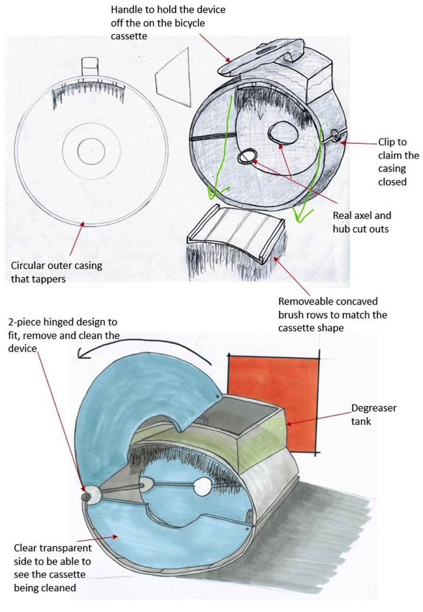
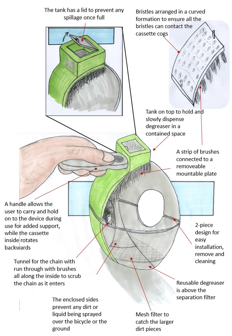
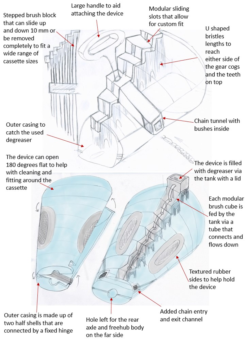
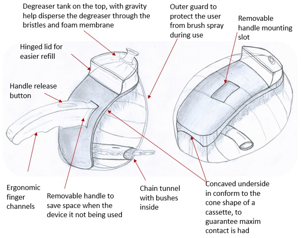
Using the collated primary, secondary research sights informed the proposed solutions, 4 potential ideas where generated, ensuring the designs were kept as close as possible to the product requirements specification. Including:
· The device can be attached and used without having to remove the back wheel, catching the dirty degreaser and water preventing drips .
· A contained design ensures no mess around the bicycle, prevent removal of greaser from bearings and brake contamination .
· The product can be fully disassembled to allow for cleaning by the user.
· Degrease and clean the chain and cassette from old lubricant, dirt and grit.
Idea 1
Idea 2
Idea 3
Idea 4
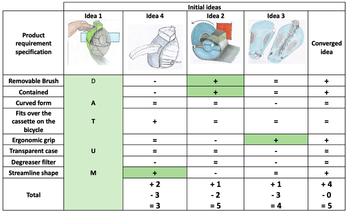
Evaluation of initial ideas - Pugh decision matrix
To choose the appropriate design, a decision matrix called the Pugh method was used. This uses the product requirement specification (PRS) and with the strongest and most favourable design as a datum. These were compared against the other ideas and scored with a plus (+) for bonus features, equal (=) to the PRS or negative (-) point, falls sort of the PRS. The advantage of the Pugh method is that it brings together the best features from all the ideas, rather rejecting them and potential missing out on additional features that bring value. The results can be seen below.
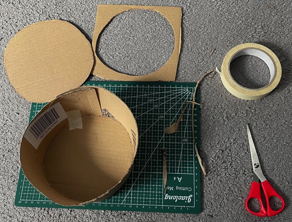
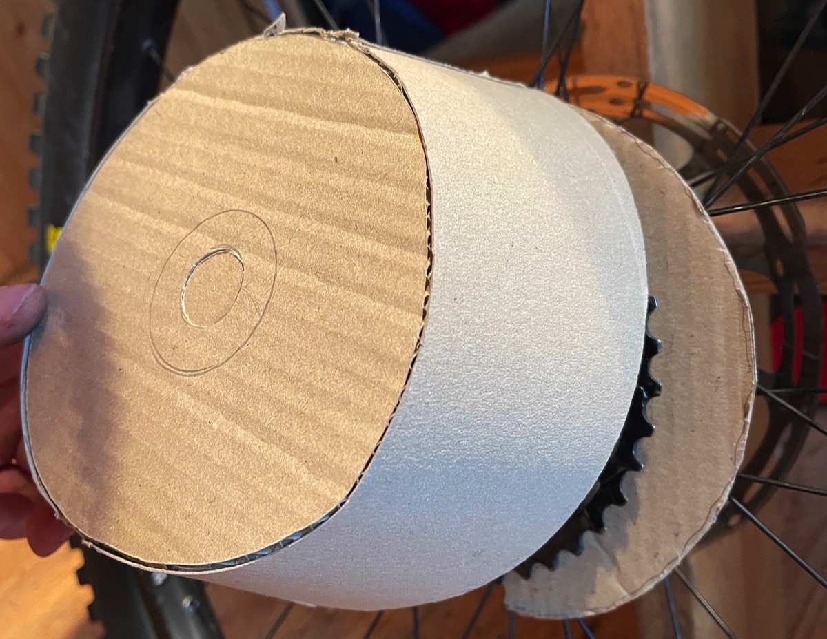
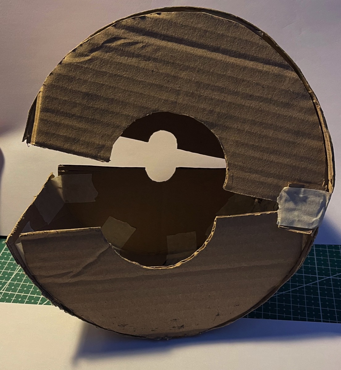
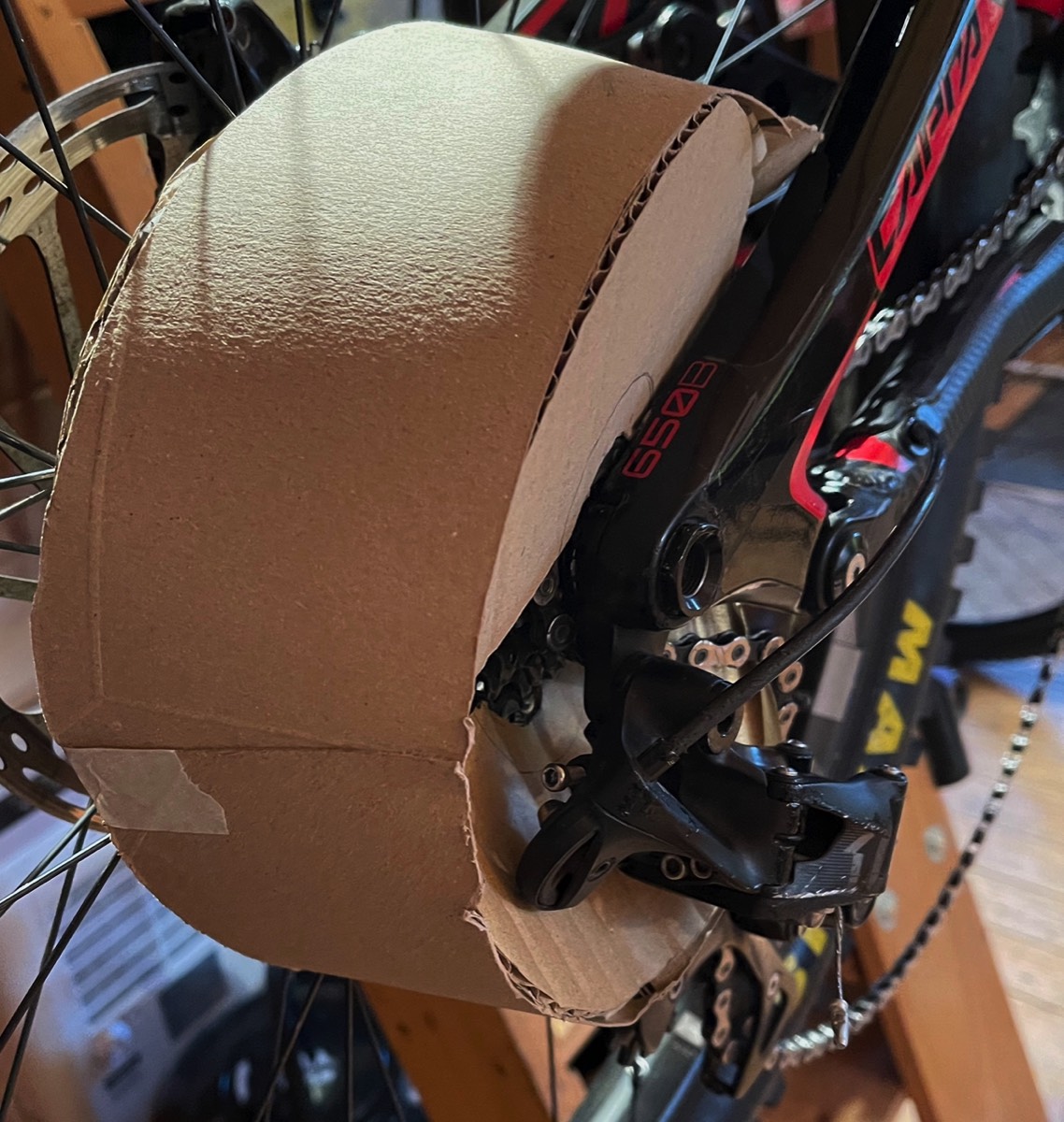
Idea development and prototyping
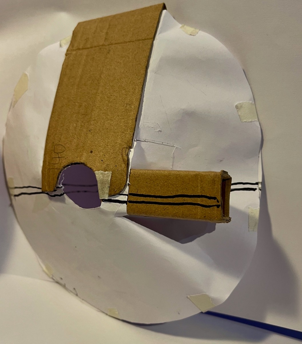
Idea 1
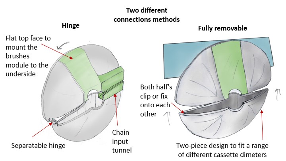
Idea 2

Further testing and refinement of idea 1
Initial 3D printed functional model
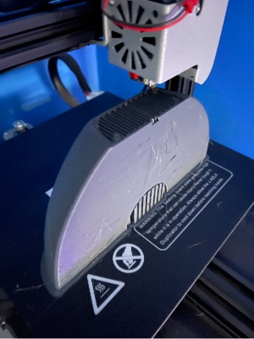
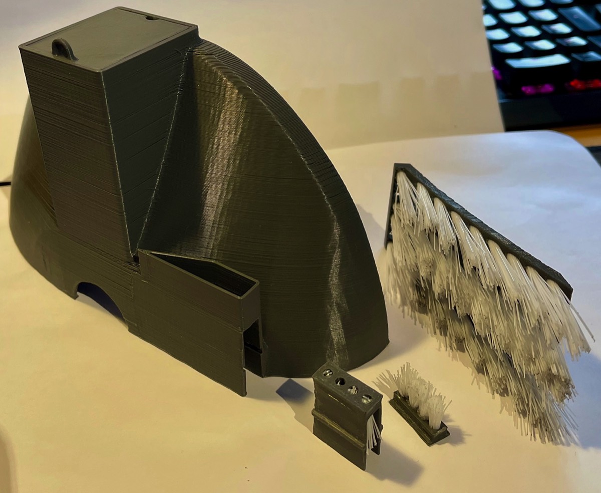
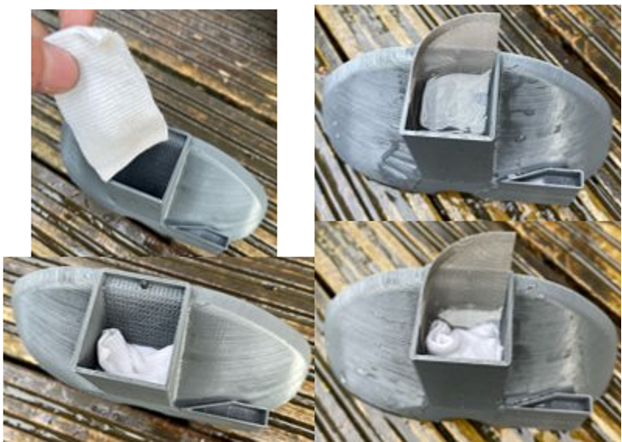
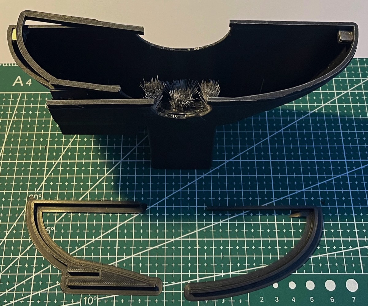
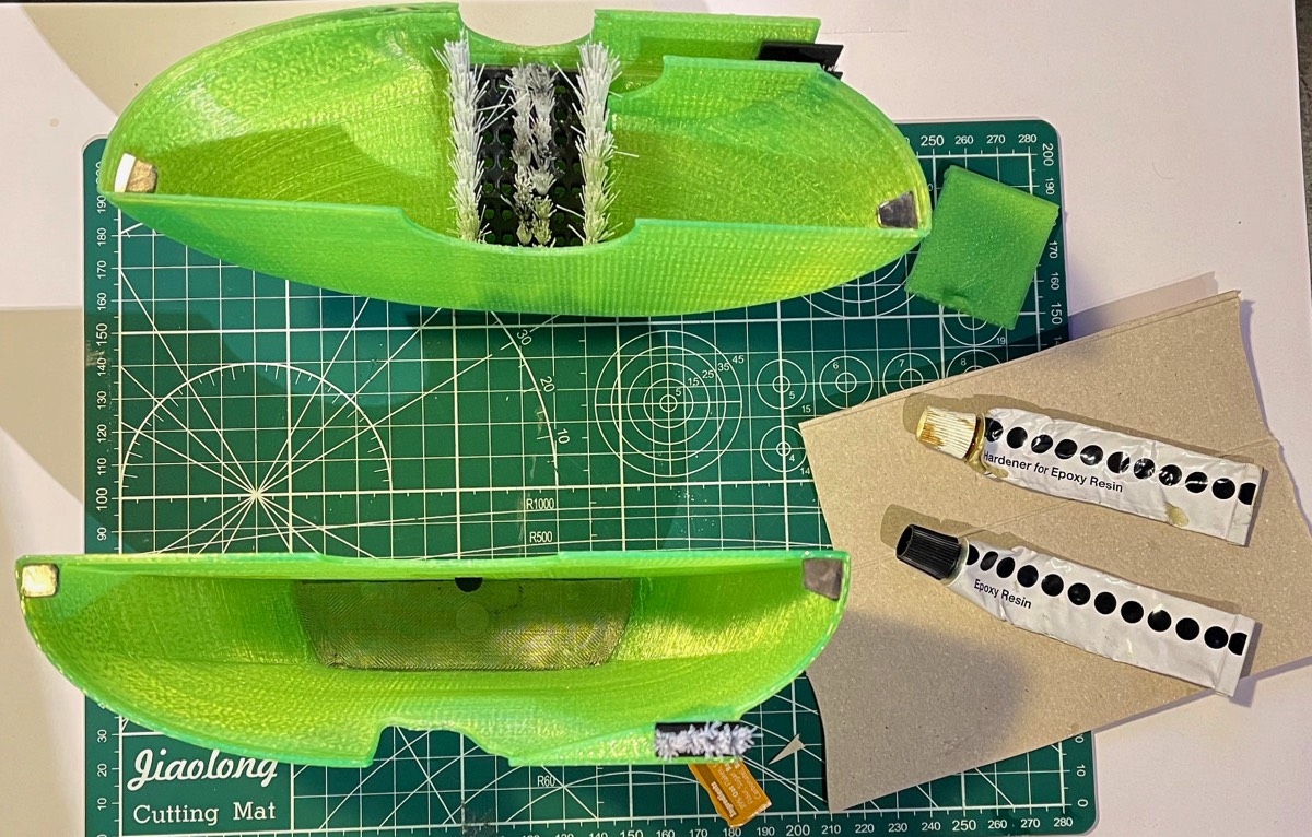
The top casing was printed first, the best orientation meant that the inside had supports to ensure the print did not collapse. The second print was the lower case that used the same orientation also requiring supports. All the other additional parts such as the lid and brushes were also 3D printed and fitted to the upper case.
Brush units assembly
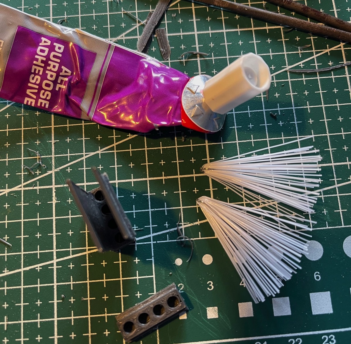
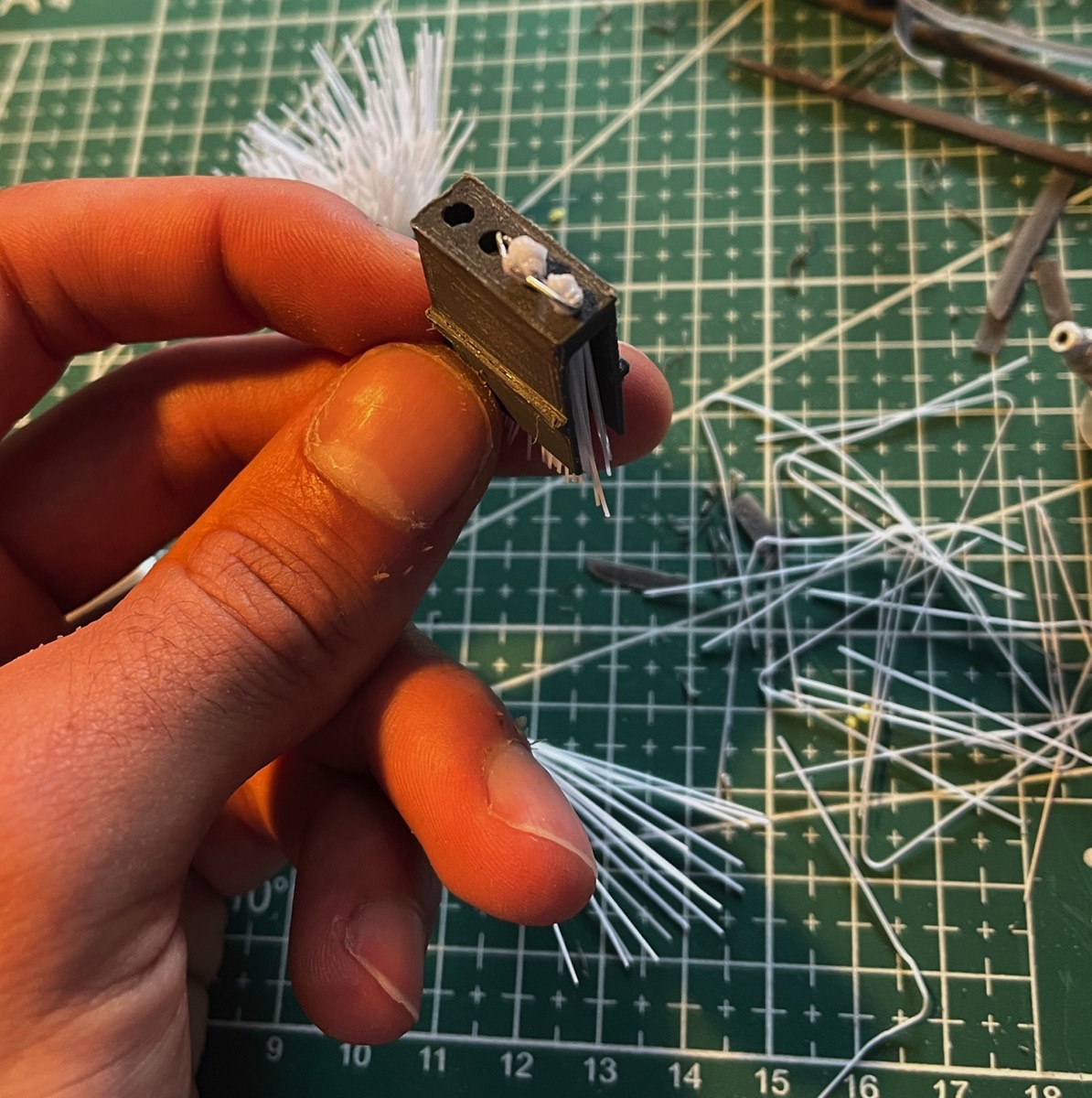
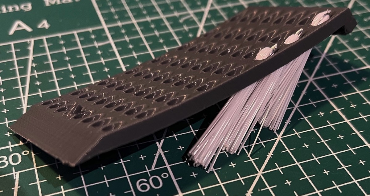
To create the brushes, bristle was removed from a washing up brush as they were made from nylon and offered the correct amount of stiffness and durability. They were then pressed into the pre-made holes and a drop of contact that sees if was added to make sure they were in securely. This process was done for the upper and lower chain brush module and the main brush block see below.
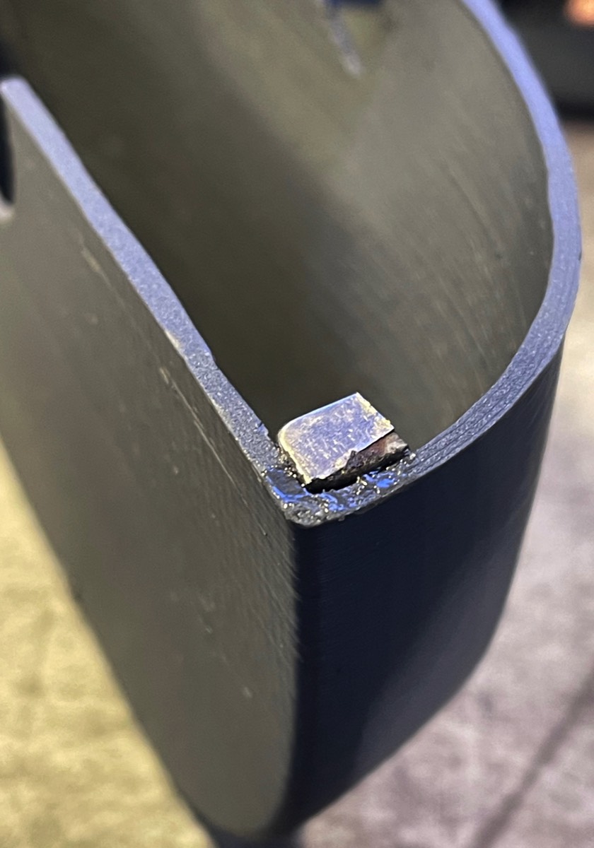
Adding magnets fasteners
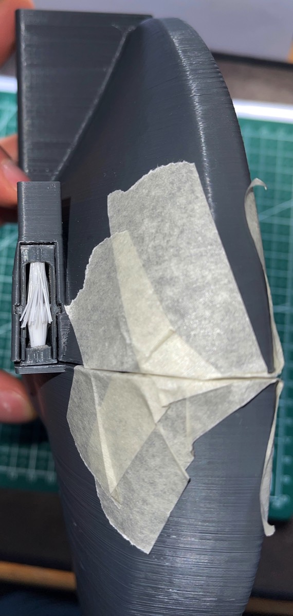
Once the brushes were all assembled the modules were place inside the upper and lower casings. As the chosen method of connection was without a hinge. Ledges were included in the CAD model so that they could have magnets blade in the corners of the cases. To ensure the magnets were orientated correctly they were first taped to ensure the polarities were correct and they were attracting and not repelling.
After the magnets well orientated and positioned correctly they were glued using epoxy resin. This adhesive was used due to the strength it provides.
After the magnets well orientated and positioned correctly they were glued using epoxy resin. This adhesive was used due to the strength it provides.
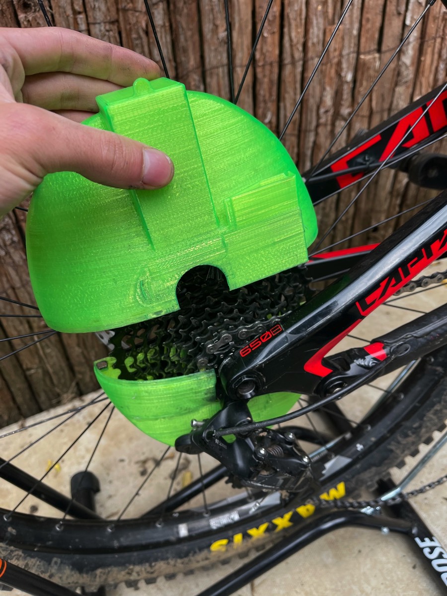
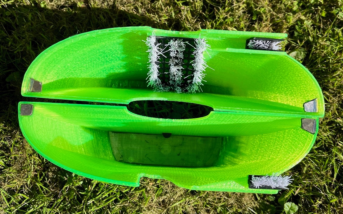
Fully constructed model
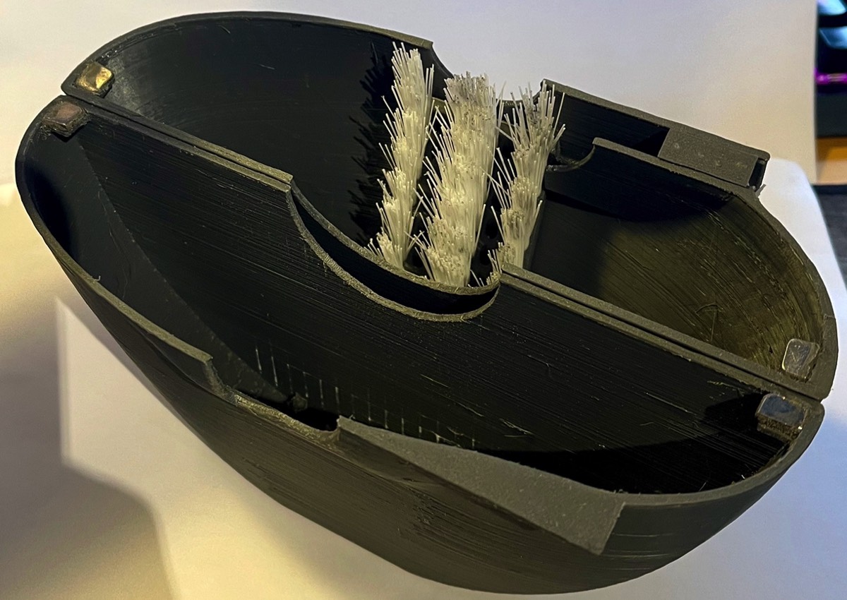
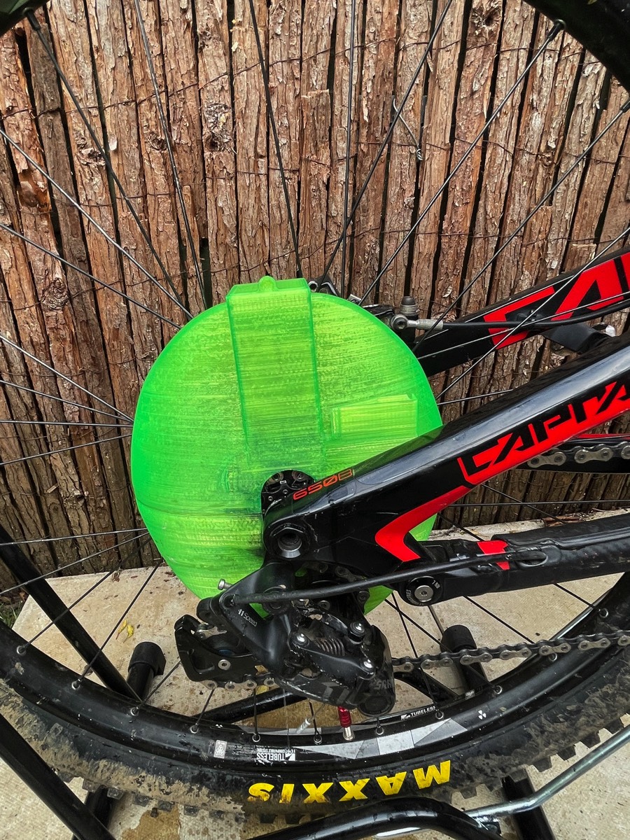
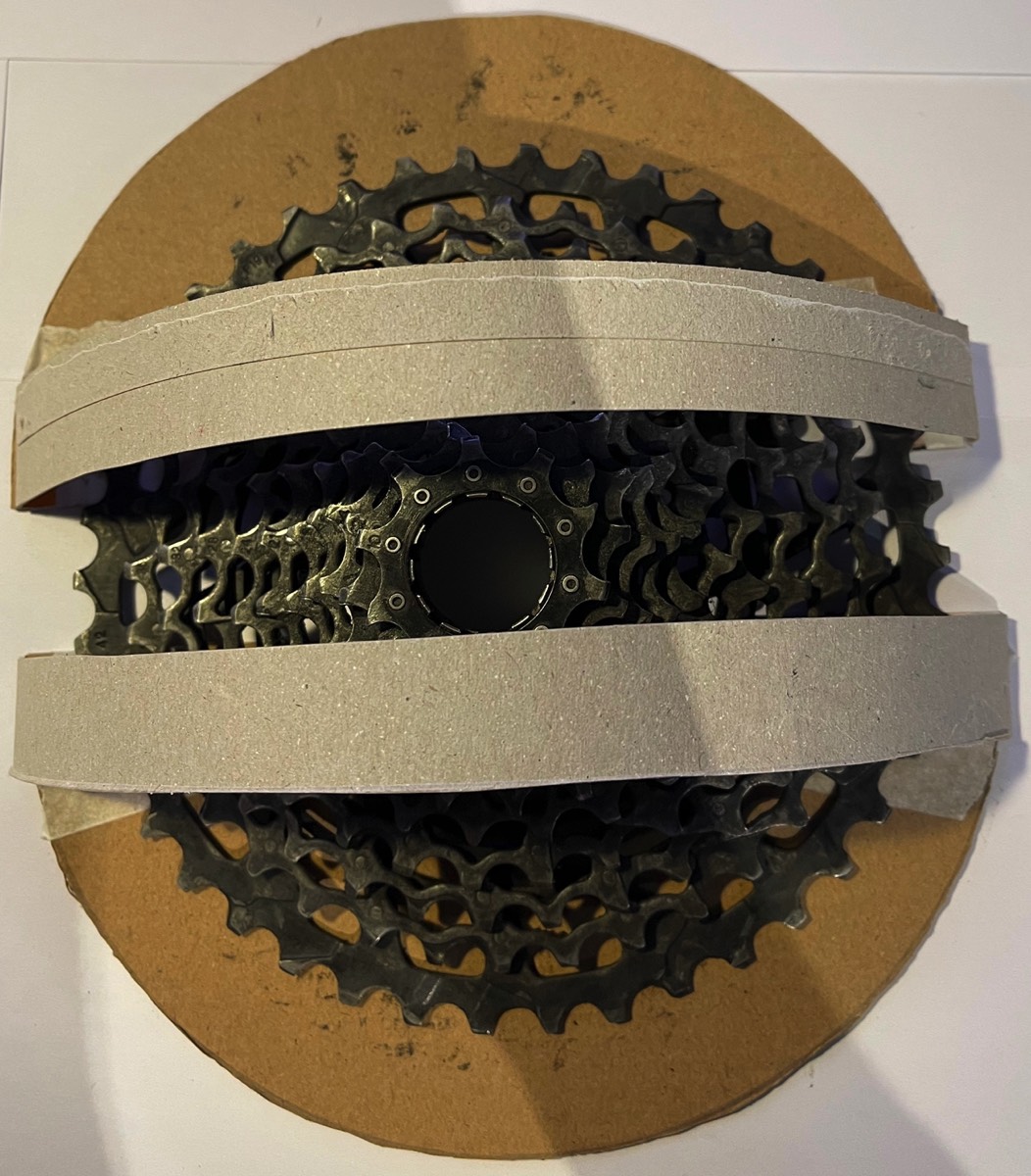
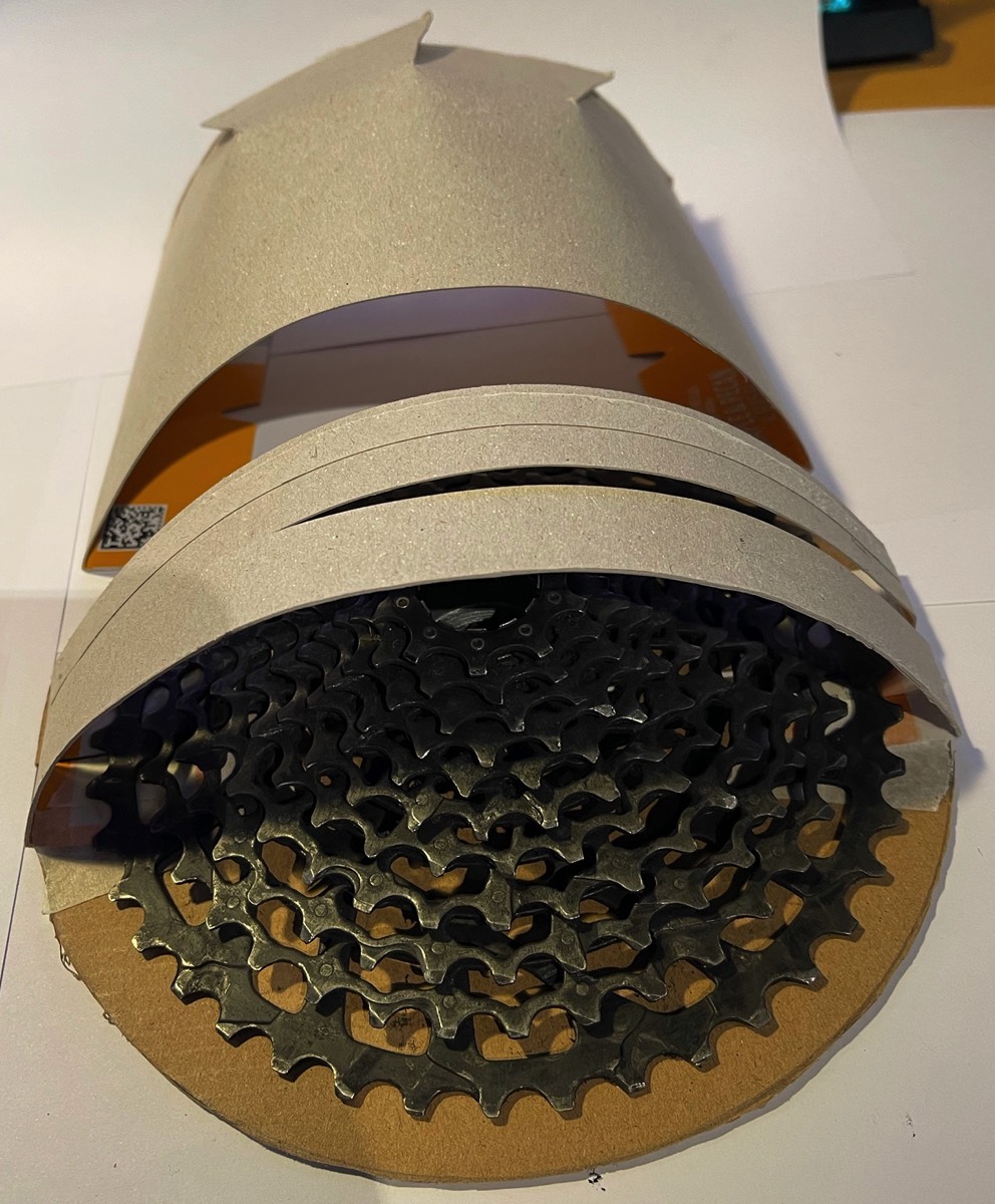
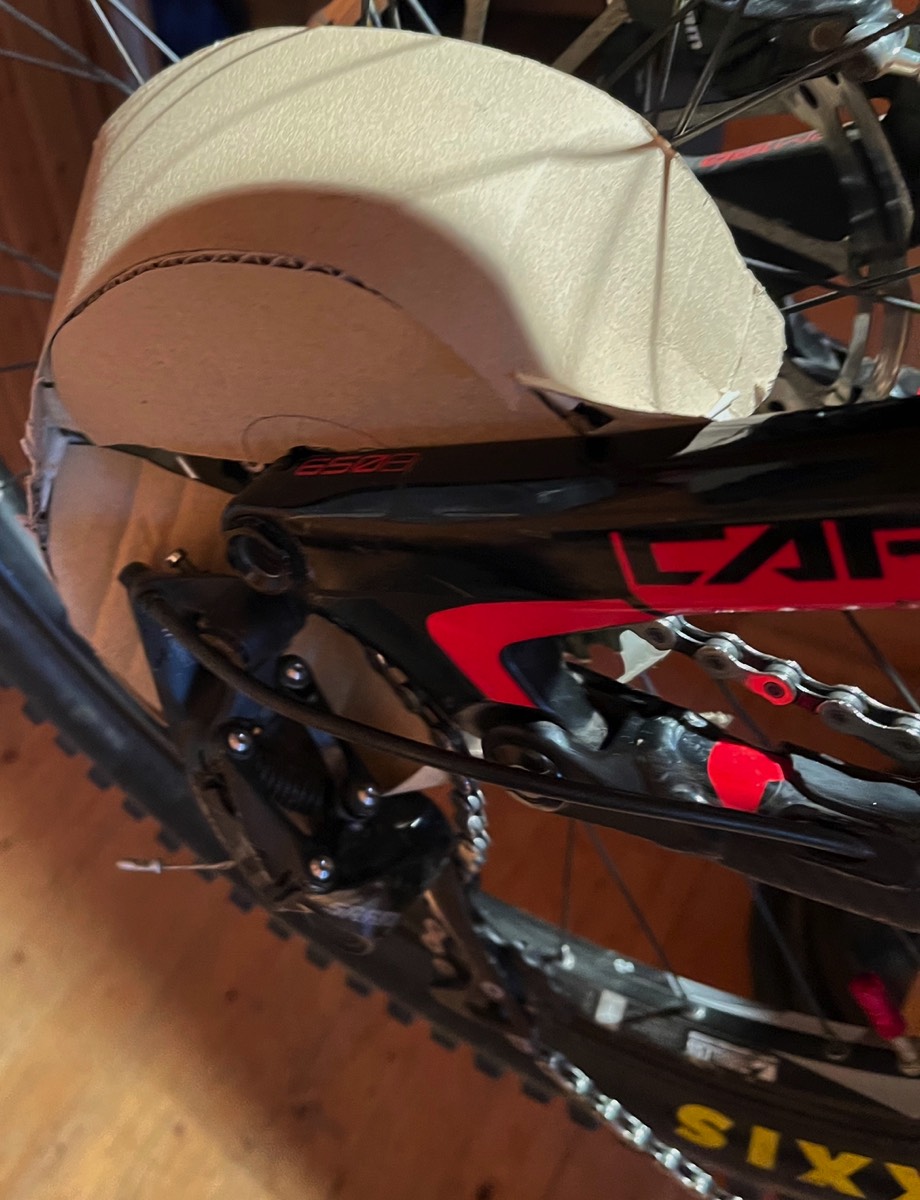
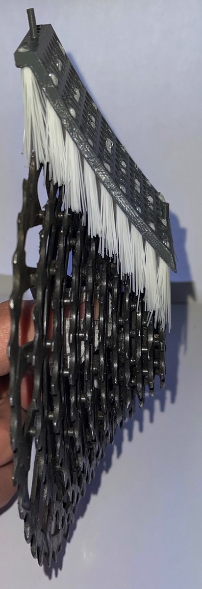
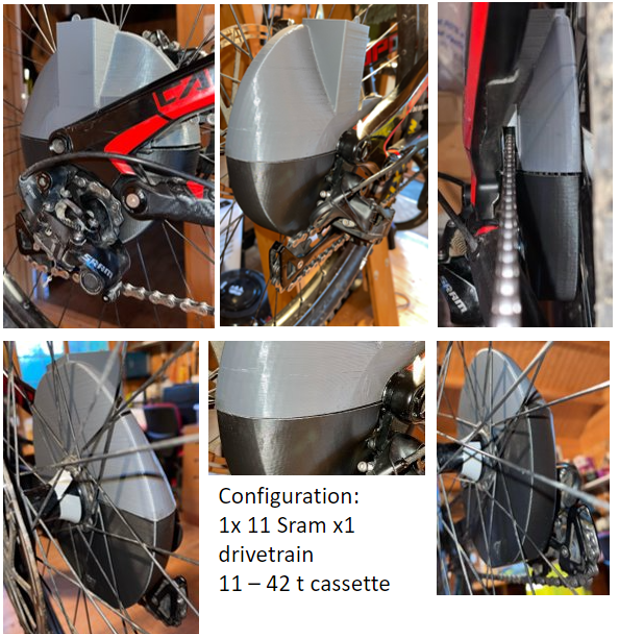
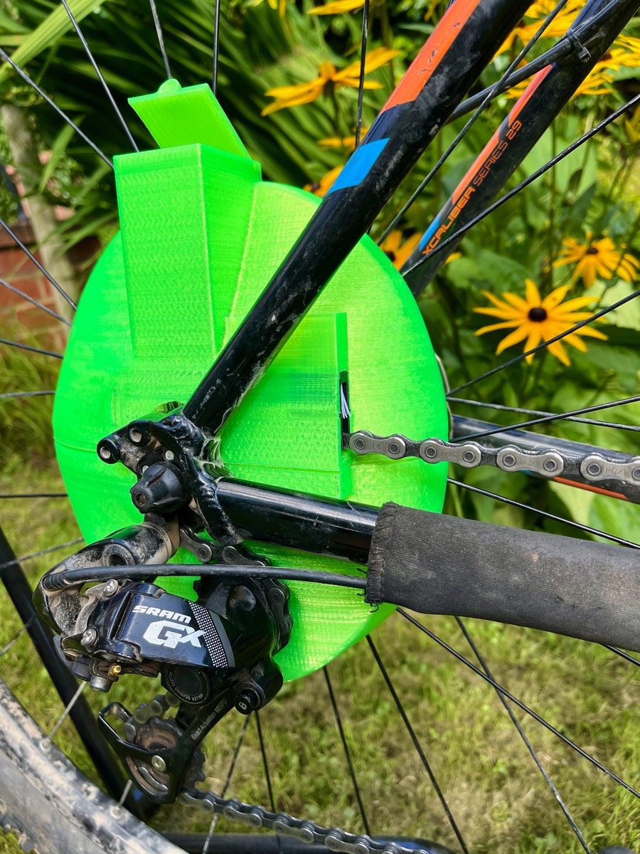
Initial test fit on a bicycle 11 speed cassette
Having the magnets in only two corns meant that the lower casing would swing open when only holding the upper case.
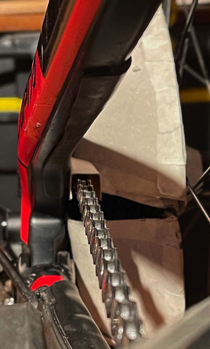
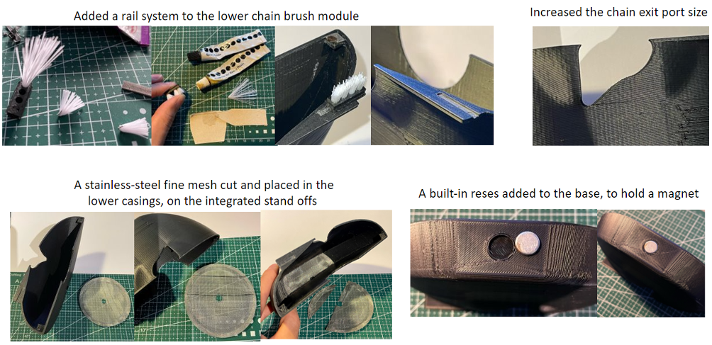
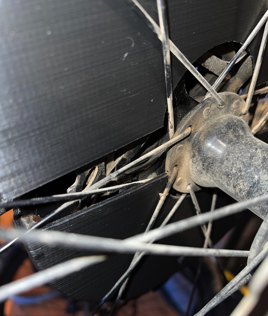
The lower case requires a larger cut out to accommodate the exiting chain angle and width. this meant that contact could not be made with the upper casing.
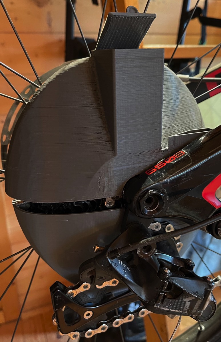
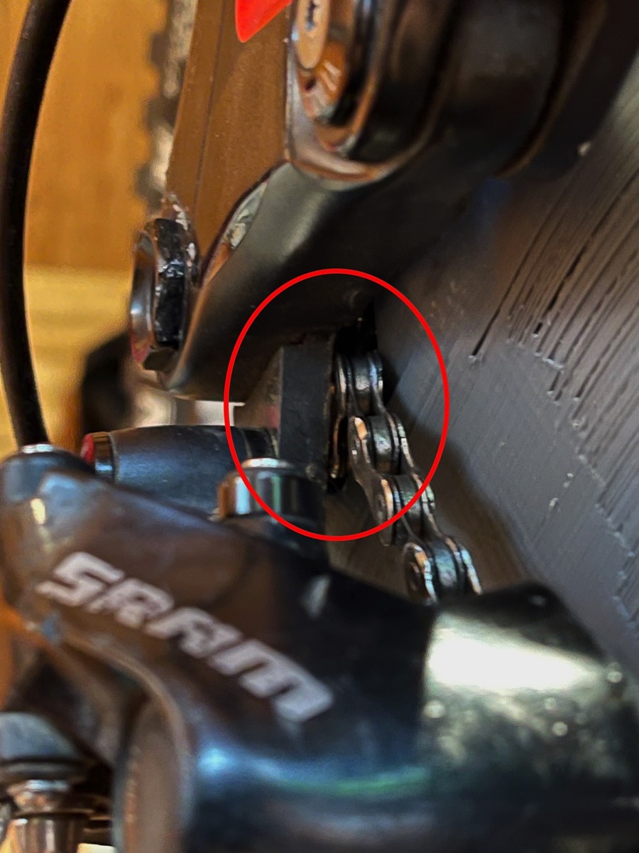
It was noticed there was clearance issues between the mech hanger and chain, meaning the lower case couldn’t marry with the upper case.
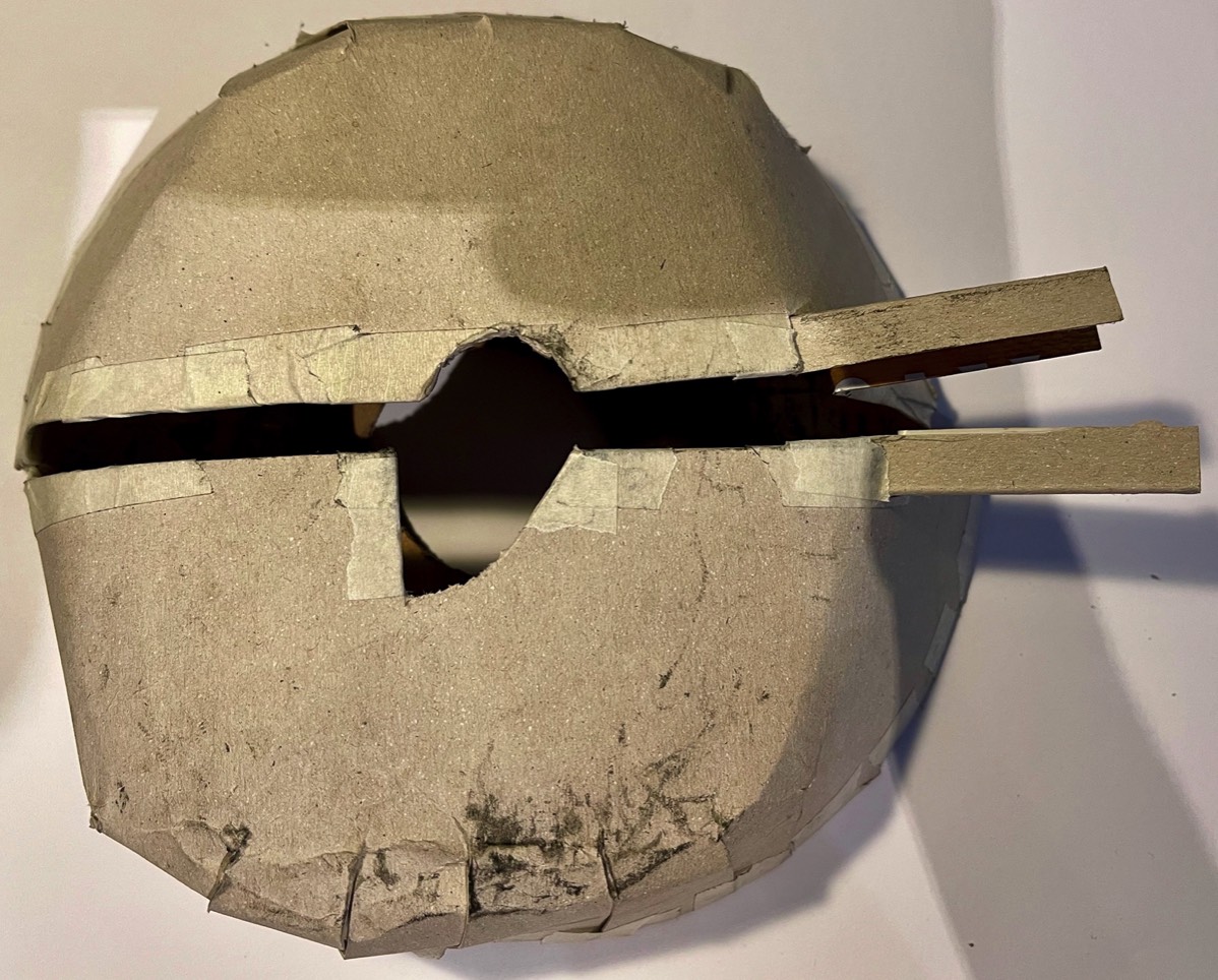
Version 2 model with modifications to improve fitment and performance
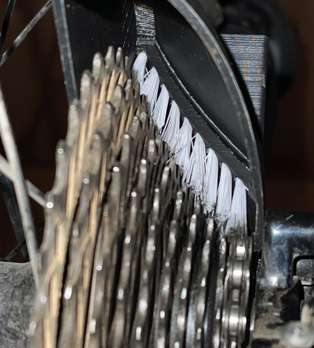
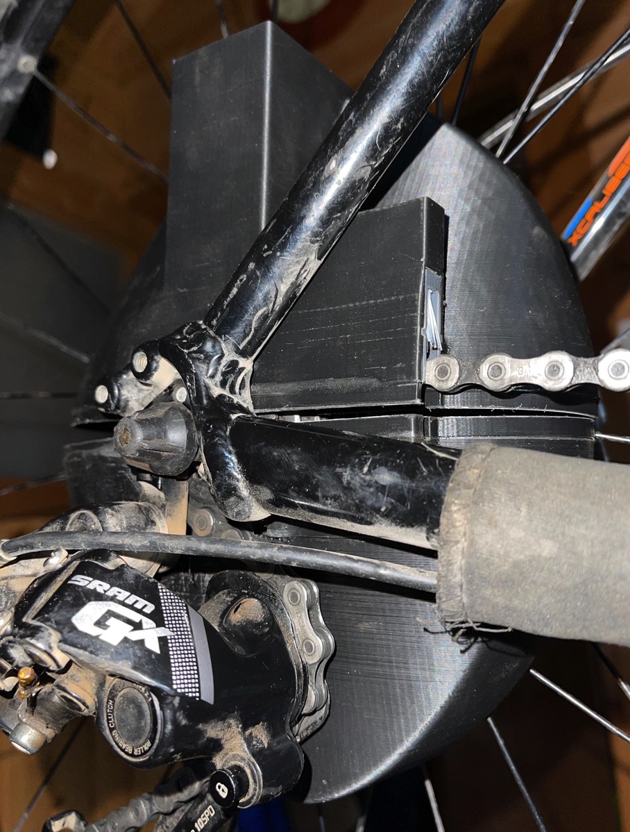
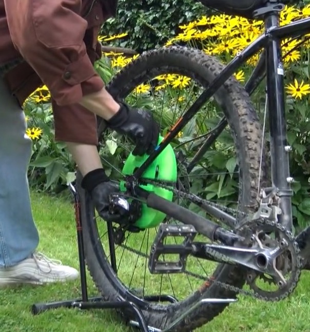
Second test fit use the improved casing
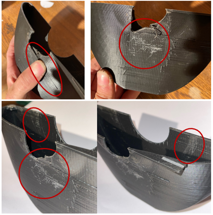
The cranks were span backwards to rotate the cassette, but not the entire rear wheel. The lower casing need a light amount of support to stay in position and not rotate out backwards.
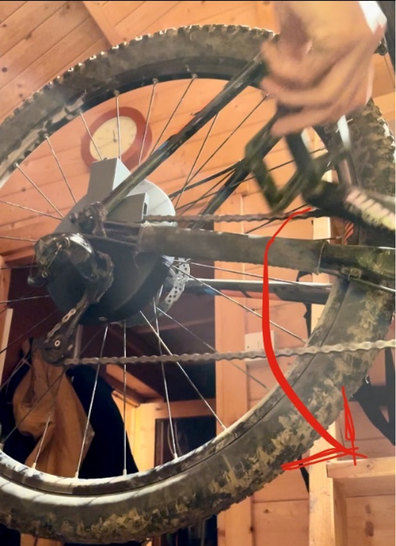
The lower casing got damaged during the rotations, however this was intentional as the markings and broken PLA parts indicated the clearance needed.
Degreaser distribution system testing
Water was added to the main reservoir to see what the drainage rate. Within 3 seconds the reservoir was empty, and the water poured directly out the bottom.
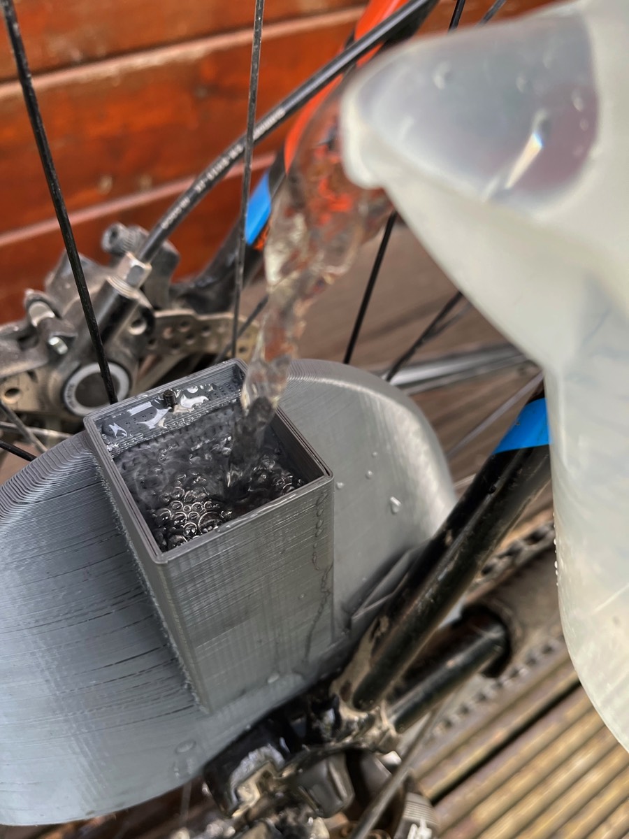
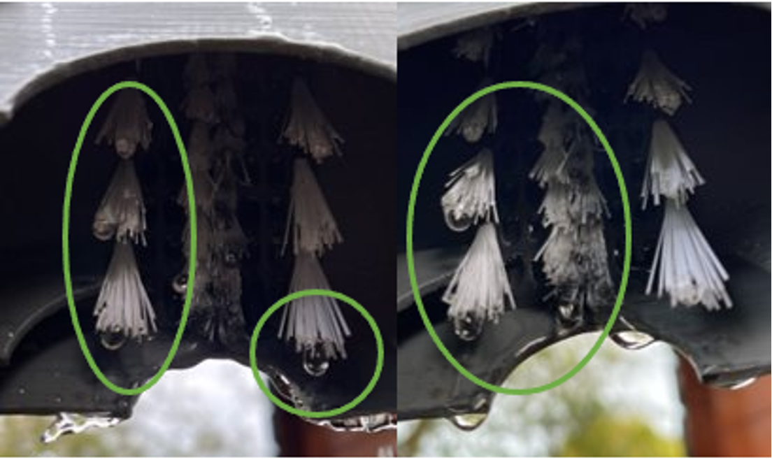
To limit the flow, rages and a mesh was added, which extended the time to 6 seconds. This meant the water had a chance to drain through more holes and drip through the bristles, just like the initial prototype.
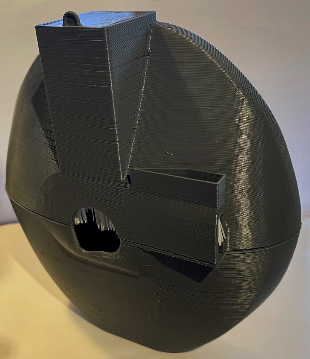
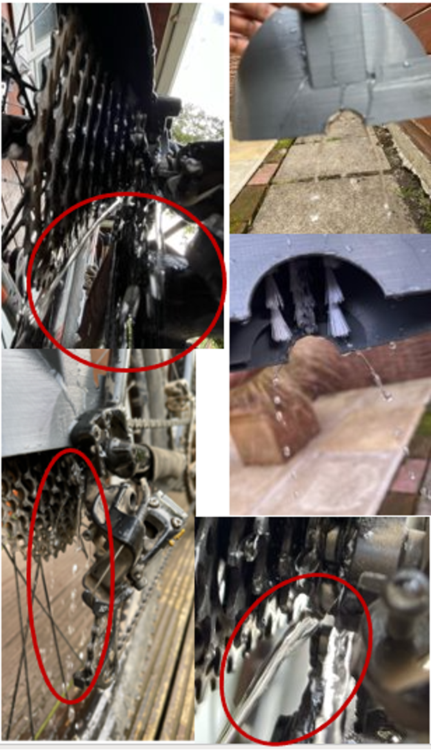
Fitment gap with brushes inside
When all the brushes where added it meant that the upper and lower cases could not close. Also, when applying any pressure to close this gap, it resulted in the cassette being jammed and not rotating backwards.

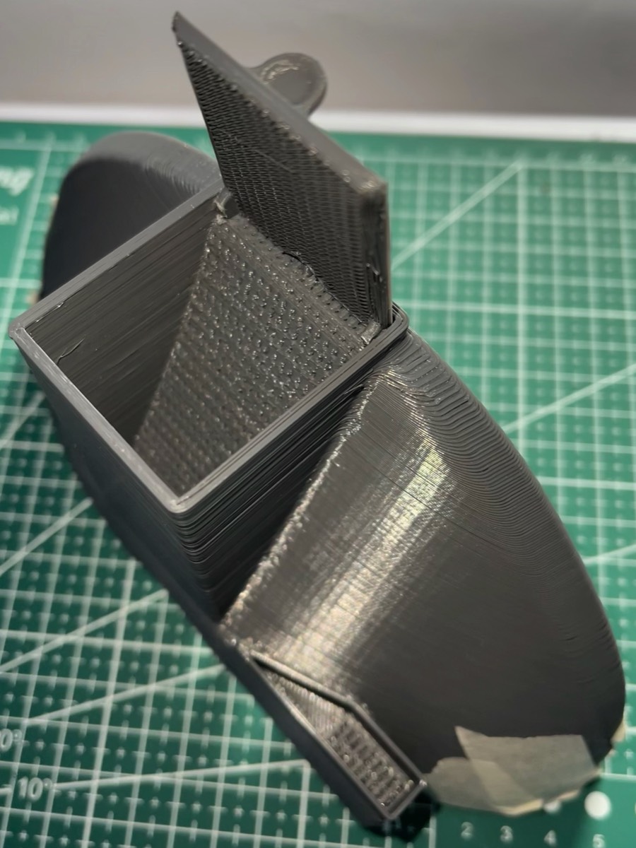
The upper and lower case tops where traced and extruded 5mm each. These spacers where then 3D printed and glued on top.
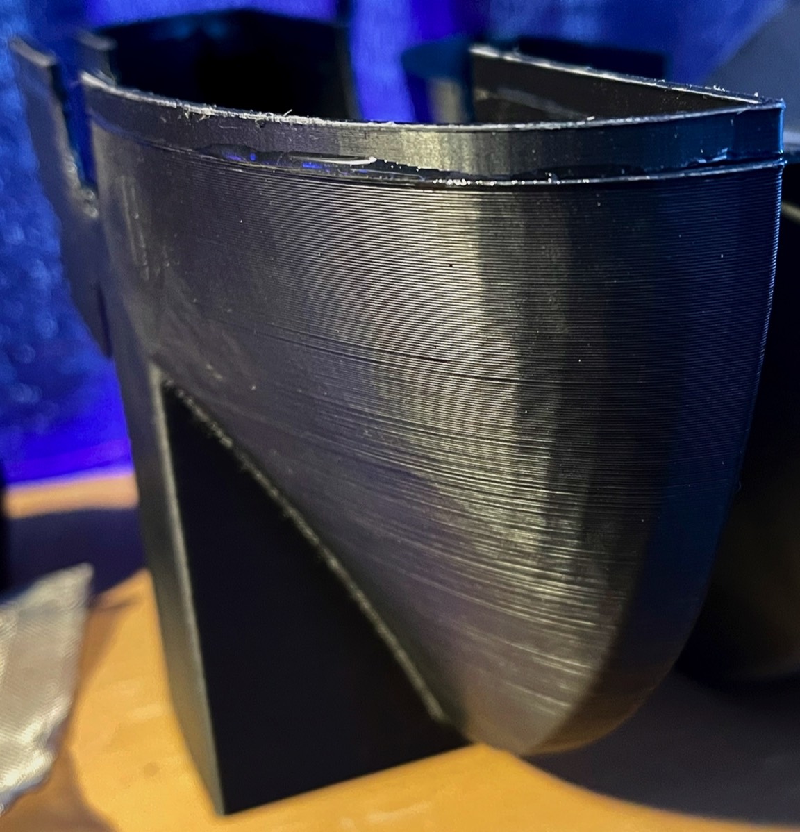
The 5mm spaces top and bottom meant the gap was reduced and without jamming the cassette. However, the gap was not entirely closed therefore 3 mm was chosen to be added to the existing 5mm.
This was process was done it small increments as it was important to apply a small amount of pressure to the cassette to make sure the brushes make good contact.
If the spacers were made too big, there would be a gap between the brushes and cassette but with no room to reduce this because of the contact between the upper and lower casings.
Prototype version 4 assembly
Proof of concept - Cleaning comparison experiment
With all the improvements and alterations that where being made it was important to verify that these changes where in fact improving the performance, usability, and functionality. To assess this a test was devised, that compared the cleanliness results of traditionally hand cleaned cassette against the prototype device.
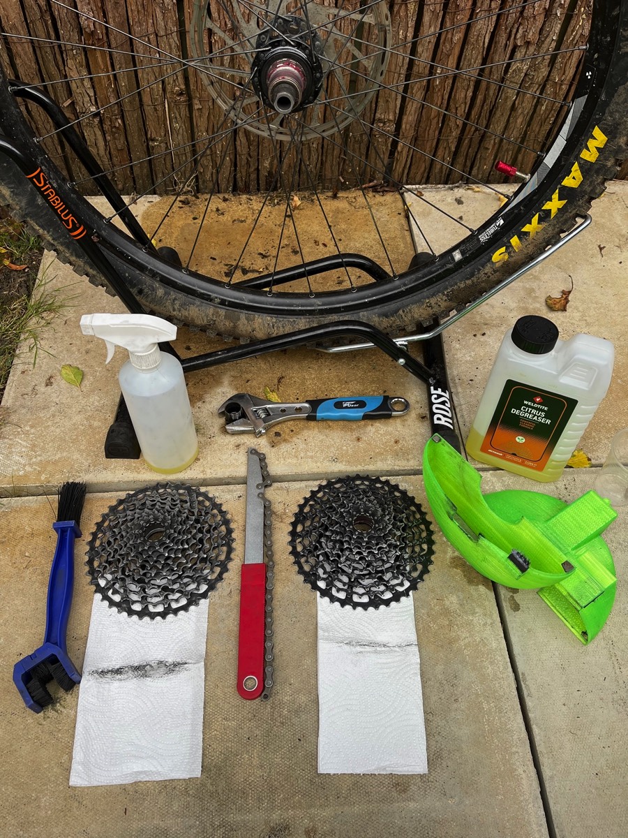
The equipment used to conduct this test was as follows:
· Prototype
· Citric degreaser
· Bicycle
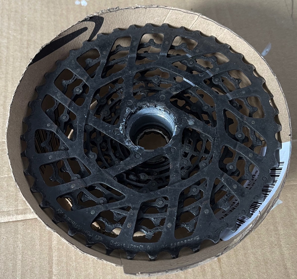
· 2x 11 speed SRAM cassettes 11-50
· Kitchen roll
· Cassette brush
· Degreaser spray bottle
· Timer
The prototype was a lot faster as to get the same result from the brush it would need to be used double the amount of time. The prototype left a flossing dirt indication mark of 9 mm and the hand brush had 18mm, double the prototype.
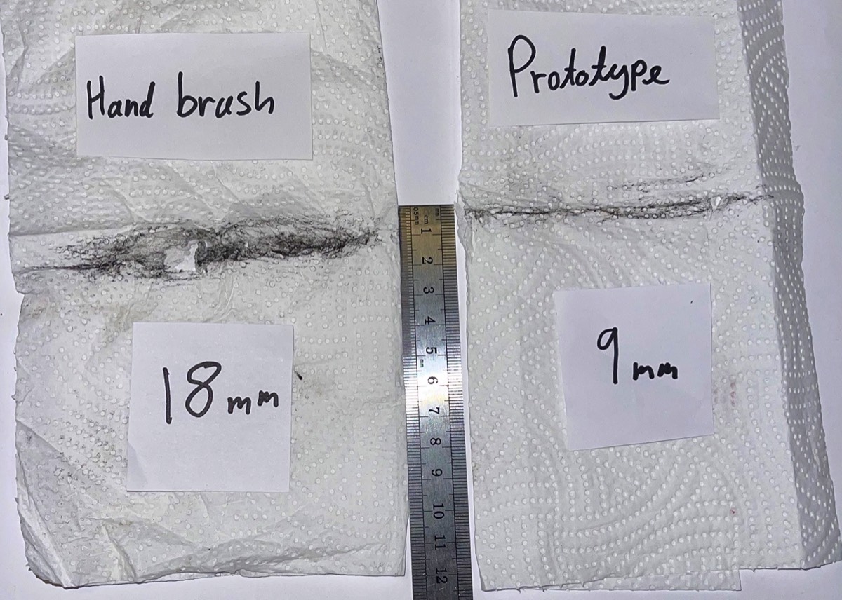
Upon reflection it was hard to accurately determine that both cassettes have the same amount of dirt on them, but both cassettes had been used and accumulated identical type of gunk. It was clear to see that the proof of concept was successful, with a clear visual difference in cleanliness. This was the outcome of the constant iterations and improvements to the prior 4 versions of the prototype.
The key insights discovered from the test was as follows:
· The prototype has a higher consistency and because this a quicker cleaning time.
· The degreaser used with the brush was lost, were as the prototype collect most of it.
Keyshot renders
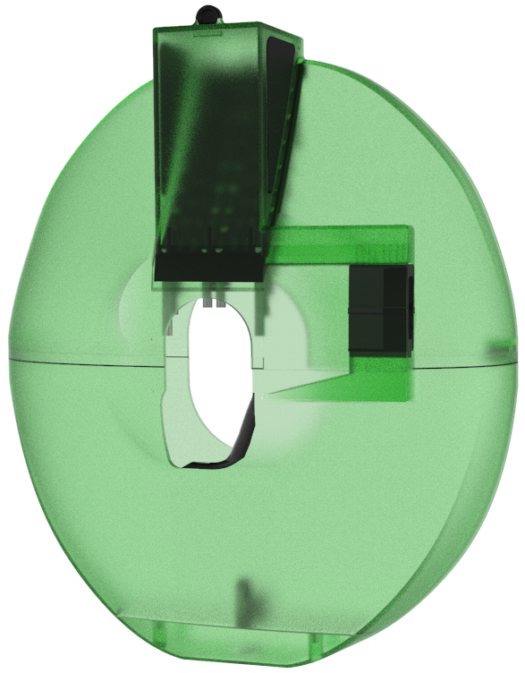
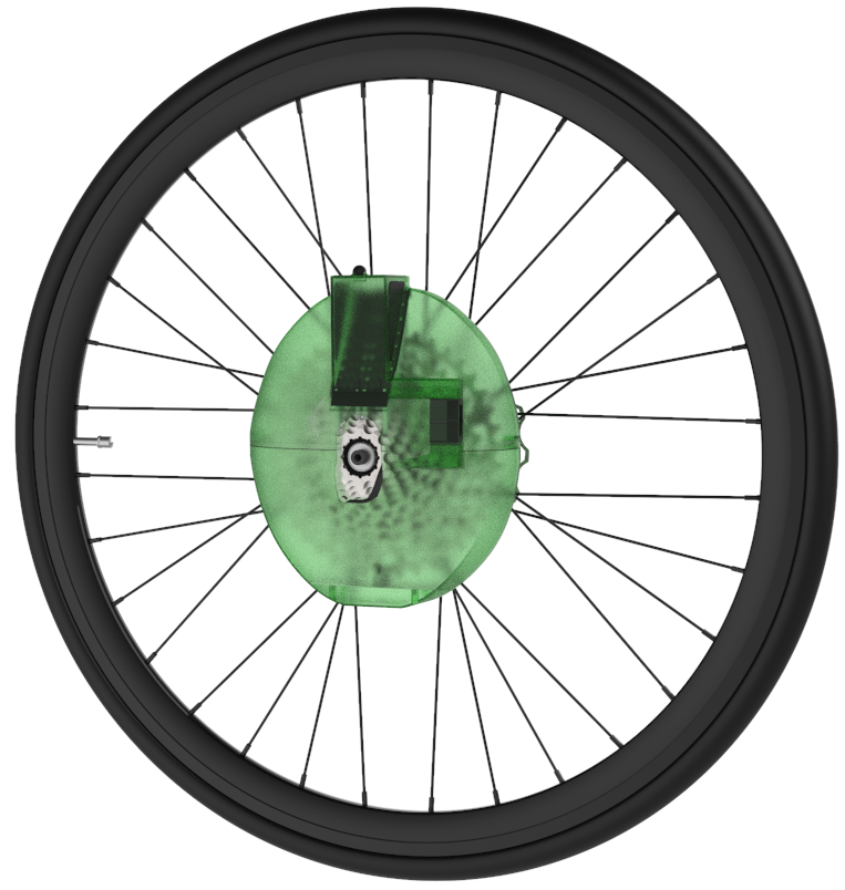
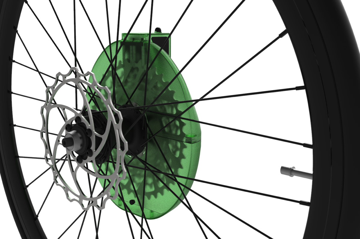
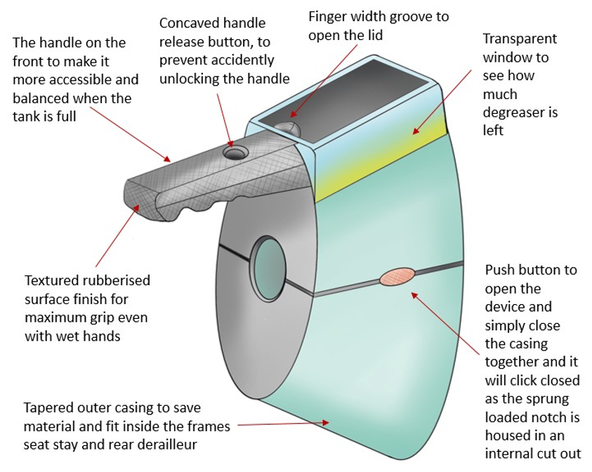
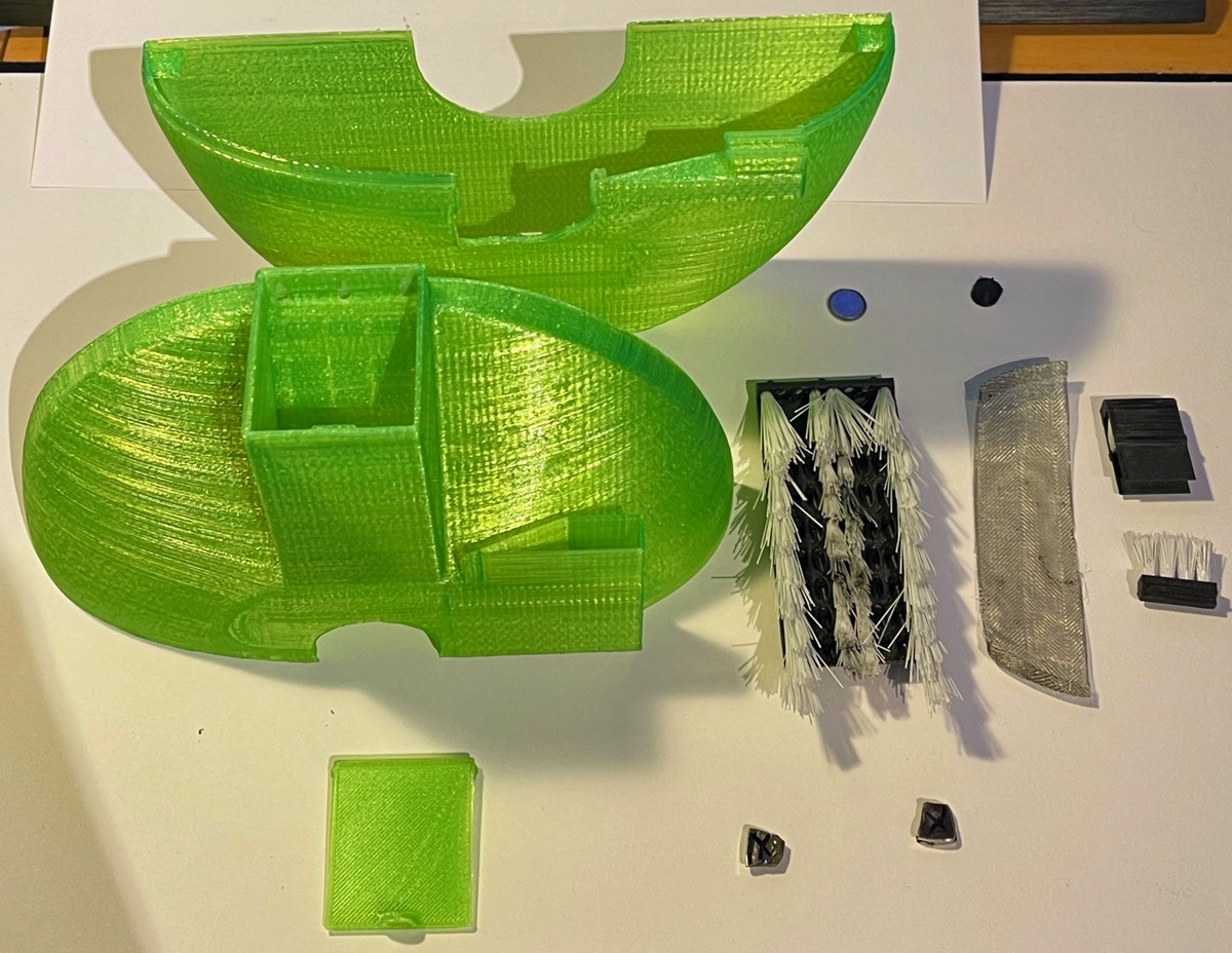
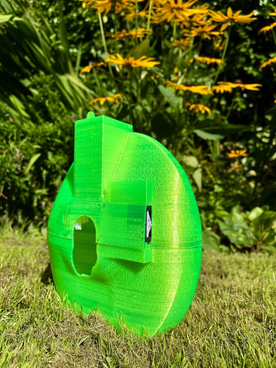
The renders show of the overall functionality, up close details of the features and the aesthetics of the applied material types. The choice of a transparent green makes the device stand out also hints at being sustainable. With the transparency acting as an additional feature to help the user operate the device, displayed in on the left. The use of the black for the brush modules creates a 2-tone colour scheme and help show the user that it they are a removable part.
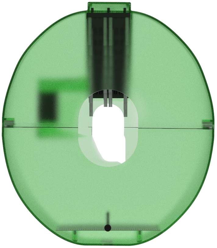
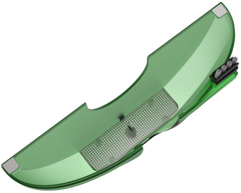
The back of the device is completely flat shown on the right. To make sure it does not get caught in the rear wheel spokes. This is particularly important during the assembly and removal stages, as any protruding parts could easily get to caught.

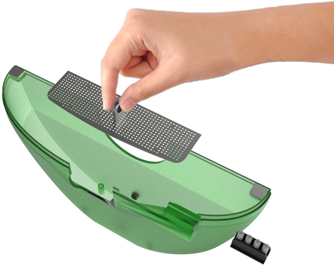
Final prototype two halves are held in place by four strong magnets either side. This means that device can be easily pulled apart with no additional buttons or clips to undo, making for a straightforward user experience, demonstrate on the right.
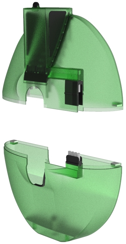
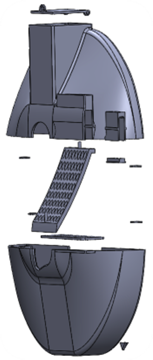
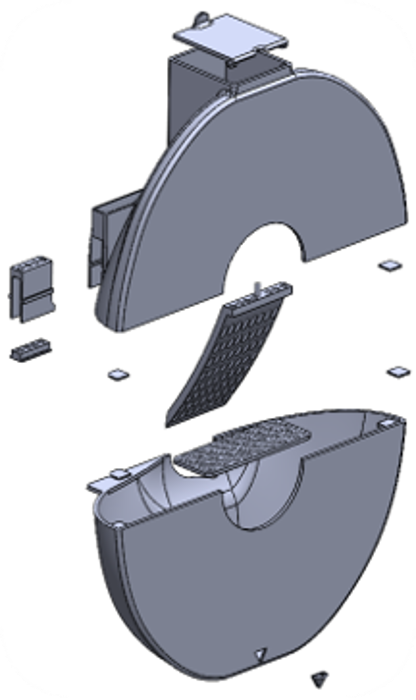
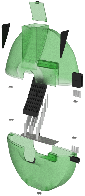
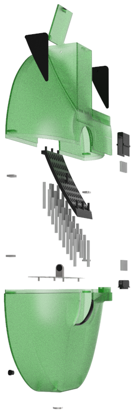
The exploded view seen on the right, shows all the parts that complete the device. These parts are as follows so two removable gripper pads a lid the upper casing, upper brush housing, bristles, main brush module, bristles call mark for magnets, lower chain brush holder, bristles, lower casing, filter and base magnet. The base magnet attracts any metal fragments that are clean off, to prevent them from contaminating the reusable degreaser.
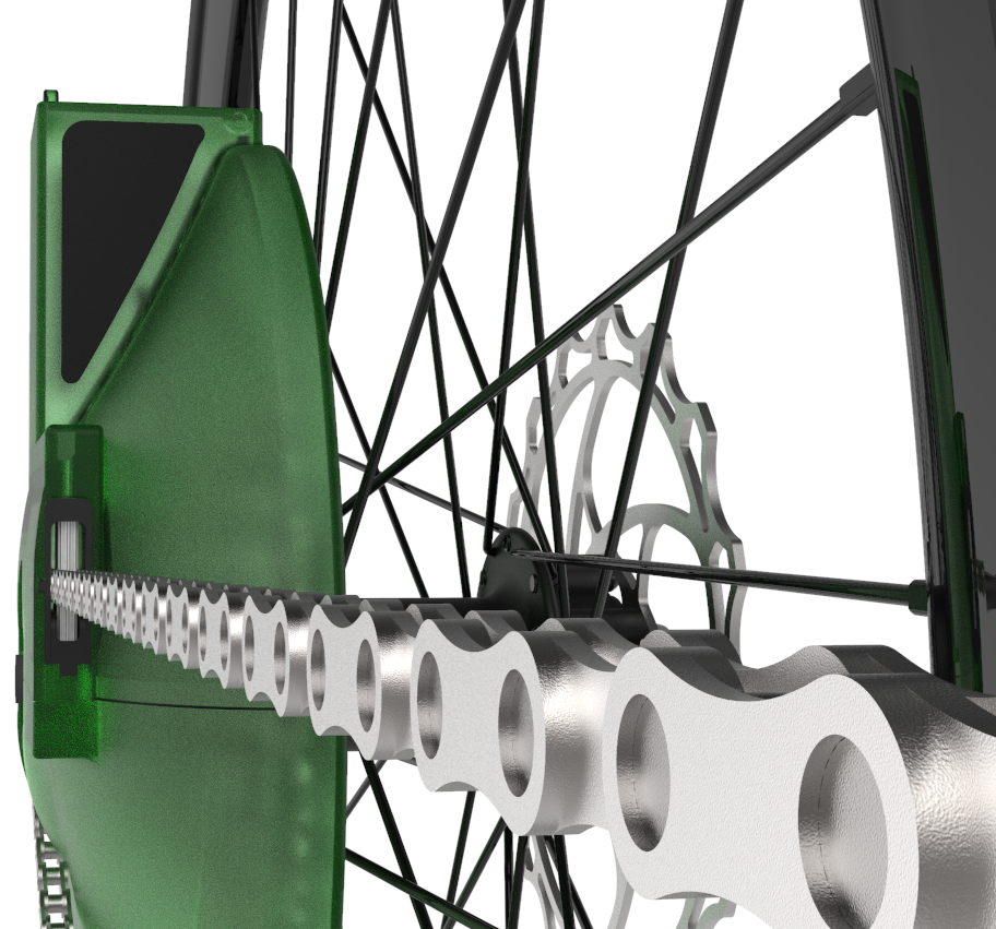
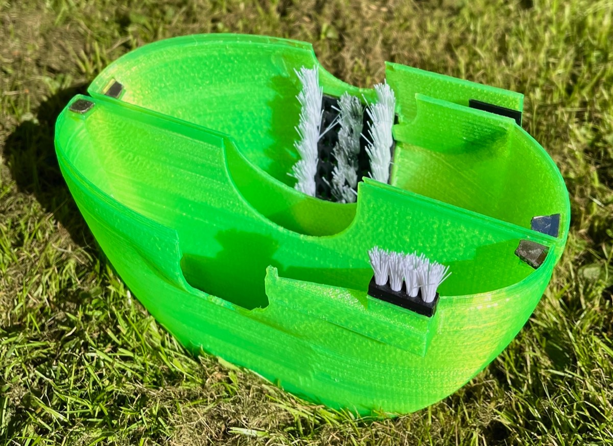
The chain is also incorporated into this cleaning device as the entry point uses upper and lower brushes to clean both sides of the chain simultaneously, shown in on the left.
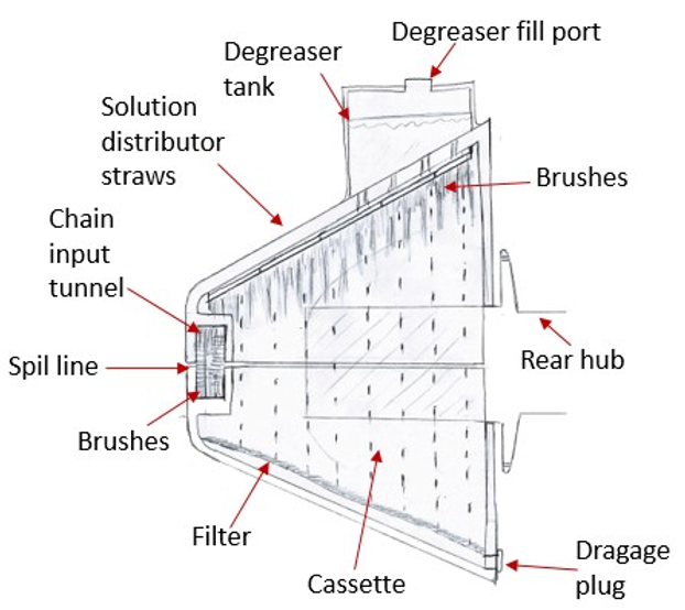
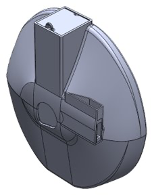
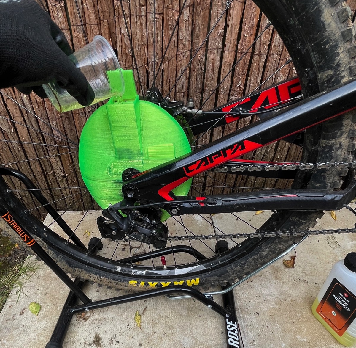
An important component that makes the reuse of degreaser feasible is due to a filter. This is placed at the bottom of the lower casing and can be easily removed via a pull tab for cleaning and disposing of the separated dirt. Also, there is a screw bung placed just above the filter on the backside to pour out the reusable degreaser after 24 hours. The filter’s purpose is to stop any sunken dirt contaminating the clean solution.
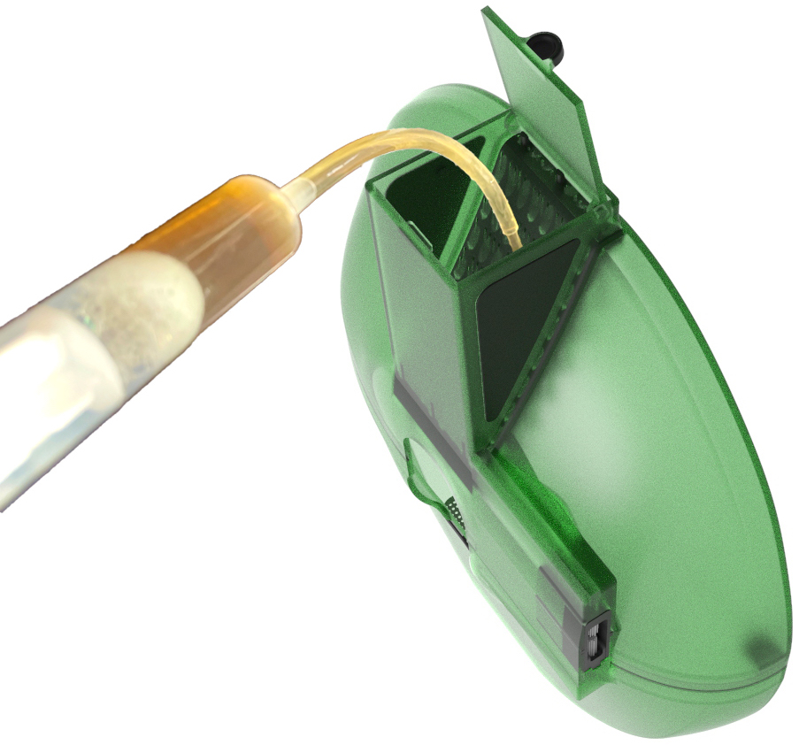
The container placed into the upper casing is the degreaser reservoir, demonstrated on the left. This hold and slowly and distributes the degreaser through 0.4mm holes placed directly about the bristles. The take can hold 50 ml, to make sure the user cannot use too much as this is wasteful and expensive. The reservoir also has a lid that should be closed during operation to ensure no degreaser is spilt, practical important when being used inside. The recommended degreaser to use with this product is citrus bicycle degreaser, because its biodegradable and safe to use on the components
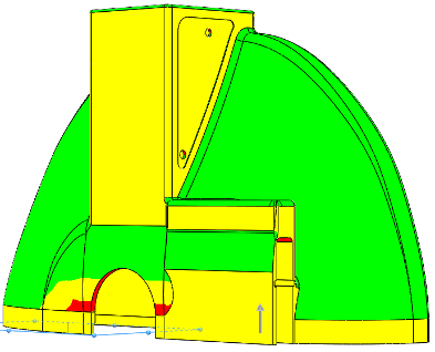
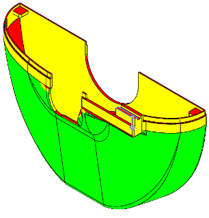
Draft analysis using Solidworks
To ensure that the casing can be injected from the mould properly a draft angle of more than 1-degree needed to be given to the surfaces, this would ensure that the part does not get wedged in the mould. To check if the current casing can be injection moulded a draft analysis was conducted using software called Soildworks. From the results seen before on the left, red areas show undercuts and the yellow areas show neutral angles that may cause the part to get stuck and green indicating area that would not get stuck.
Before
After
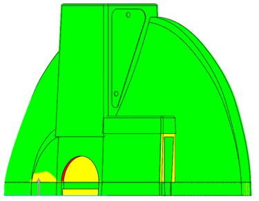
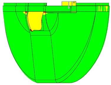
Using a draft tool in SolidWorks, 2-degree drafts were added to each of the necessary surfaces. The analysis was then run again to check to validate if this done correctly. The after on the right shows the results of the second draft analysis with an increased amount of green.